How to Draft a Pocket Knife Product Specification for Custom Artwork and Tolerance Control
How to Draft a Pocket Knife Product Specification for Custom Artwork and Tolerance Control
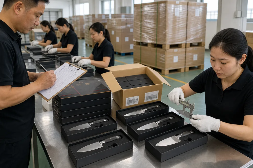
A pocket knife product specification should define the exact product being customized, every approved change, the file controlling each artwork location, the features subject to tolerance control, and the evidence required for acceptance.
Replace vague instructions such as custom logo, centered blade, premium finish, or tight fit with controlled references, measurable limits, defined inspection conditions, and traceable approval records.
This drafting framework does not prescribe universal knife tolerances, decoration capabilities, sample sizes, or acceptance limits. Complete those values only after identifying the baseline product, intended design, proposed manufacturing process, and inspection method.
The cited sourcing pages provide limited background context:
- A wholesale sourcing guide lists steel, lock, finish, packaging, MOQ, Incoterm, and inspection among the topics buyers may address Vast State. Keep commercial terms on the RFQ or quotation cover sheet and place product requirements in the controlled specification.
- A wholesale category overview describes multiple knife categories rather than treating knives as one product type SZCO. A product specification should therefore identify the exact pocket knife platform instead of relying on a general product name.
- A sourcing-resource index separates product, logo, packaging, and carton customization into distinct topics China Knives Wholesale. The specification should likewise assign separate requirement IDs, files, and approvals to those workstreams.
These sources do not establish the correct material, decoration process, dimensional tolerance, test method, or acceptance limit for a particular knife. Define those entries in the project documents and resolve them through the supplier response and approval process.
1. Freeze the Pocket Knife Baseline
Customization cannot be controlled until the underlying product is identified. Record one of the following project routes as a document-control label, not as a universal industry classification:
- **Decorated stock model:** The identified product configuration remains unchanged except for specified marks, colors, or packaging artwork.
- **Modified stock platform:** Listed components, materials, finishes, hardware, clip configuration, or other features differ from the identified baseline.
- **Buyer-defined design:** Buyer-controlled drawings, a bill of materials, and related specifications define the product.
Complete the specification header before releasing artwork or tolerance requirements:
| Control field | Required entry | |---|---| | Project identity | Project code and controlled product name | | Specification identity | Document number, revision, issue date, and revision owner | | Project route | Decorated stock model, modified stock platform, or buyer-defined design | | Baseline product | Supplier model and revision, approved reference-sample ID, or buyer drawing and revision | | Configuration | Blade, handle, liner, lock, pivot, fastener, clip, spacer, and other applicable component references | | Variant scope | SKU, colorway, artwork version, packaging version, and quantity by variant | | Governing files | Exact drawing, artwork, finish, packaging-artwork, and inspection file names and revisions | | Required approvals | Engineering, decorated, packaging, and final integrated samples as applicable | | Supplier response | Compliance confirmation, numbered deviation, or clarification request by requirement ID |
For a stock platform, record the supplier model and the specific sample or catalog revision reviewed by the buyer. For a buyer-defined product, attach the applicable assembly drawing, component drawings, and bill of materials. Do not use a photograph or uncontrolled product name as the sole geometry reference.
Assign document precedence by requirement type
Do not state that one physical sample overrides every controlled document. Assign a governing reference to each requirement class:
| Requirement class | Governing reference | |---|---| | Dimensions and tolerances | Released drawing and critical-to-quality schedule | | Product configuration | Bill of materials and customization matrix | | Artwork geometry | Approved production artwork file | | Artwork size and placement | Artwork-location drawing and associated callout | | Color, texture, and gloss | Named appearance reference and stated review conditions | | Packaging graphics | Approved dieline and packaging-artwork file | | Physical appearance | Identified appearance or boundary sample, limited to attributes listed in its approval record | | Exceptions | Signed deviation identifying affected requirement IDs and revisions |
Require written resolution when controlled references conflict. A physical sample should govern only the attributes assigned to it; it should not silently replace a numerical tolerance, material callout, or later artwork revision.
2. Map Every Customization Against the Baseline
Use one customization matrix to show all requested changes. Include deliberately unchanged items where omission could create ambiguity.
| Item | Baseline condition | Required condition | Governing reference | Approval evidence | |---|---|---|---|---| | Blade | Identified baseline | Material, profile, finish, marking, or explicit unchanged status | Drawing, bill of materials, and finish schedule | Engineering or decorated sample as applicable | | Handle or scales | Identified baseline | Material, color, texture, contour, insert, or unchanged status | Component drawing and appearance reference | Material, finish, or assembled sample | | Liner and spacer | Identified baseline | Material, finish, thickness, geometry, or unchanged status | Drawing and bill of materials | Engineering sample and measurement record | | Pivot and fasteners | Identified baseline | Finish, color, head style, position, or unchanged status | Bill of materials and drawing | Assembled sample | | Clip | Identified baseline | Side, orientation, position, shape, finish, or unchanged status | Clip or assembly drawing | Engineering sample | | Product artwork | Baseline mark or no mark | Process, file revision, finished dimensions, position, orientation, and appearance requirement | Artwork package | Proof and decorated sample | | Packaging artwork | Baseline packaging | Dieline, graphics, barcode area, and variant mapping | Packaging-artwork package | Proof and assembled packaging sample |
Require one supplier response for every row:
- Compliant as specified
- Proposed deviation
- Clarification required
A proposed deviation should identify the affected requirement ID, proposed alternative, reason, and every drawing, artwork file, sample approval, or inspection instruction requiring revision. It becomes part of the product specification only after the buyer records its disposition and updates the affected control documents.
3. Write Atomic, Inspectable Requirements
Assign each requirement a stable ID. Where practical, keep one acceptance decision in each requirement so that failures and deviations can be dispositioned independently.
Use this structure:
**Requirement ID + component or feature + required result + governing reference + limit + inspection condition + method + required evidence.**
A requirement register can follow this format:
| ID | Controlled requirement | Supplier return | Acceptance basis | |---|---|---|---| | BASE-01 | Exact baseline model, revision, and reference-sample ID | Written confirmation | Released specification identifiers | | CUS-01 | Named component and required change from baseline | Compliance response and proposed process | Released customization matrix | | ART-01 | Artwork file, decorated face, process, size, position, orientation, and restricted area | Proof, process confirmation, and decorated sample | Released artwork package and callout limits | | FIN-01 | Component, finish, color reference, texture reference, and review conditions | Finish sample or identified appearance reference | Released finish schedule | | CTQ-01 | Feature, datums, product state, nominal value or boundary, tolerance, and method | Measurement result | Released drawing and CTQ schedule | | FUN-01 | Product state, fixture, applied action or load, measurement point, and pass/fail limit | Functional inspection record | Released test instruction | | PKG-ART-01 | Dieline, artwork revision, panel, barcode area, and variant mapping | Proof and assembled sample | Released packaging-artwork package |
For example:
ART-01 — On the blade presentation face, artwork file [file name and revision] shall have a finished width of [nominal] mm with a tolerance of [value] mm. The defined artwork origin shall be located X = [value] mm and Y = [value] mm from datums A and B on drawing [file name and revision]. Inspect with the blade in [defined state] using [method]. Record the measured width, X position, and Y position.
The values remain project-specific, but the sentence establishes the information required for an inspectable artwork requirement.
Avoid combining unrelated acceptance decisions. Artwork size, location, orientation, color, legibility, and surrounding surface damage may need separate requirement IDs because they can have different references, inspection methods, and dispositions.
4. Build a Controlled Artwork Package
Identify product artwork, retail-packaging artwork, and carton artwork separately. An approval should apply only to the item, artwork ID, and revision named in the approval record.
Define the artwork file set
For each graphic, include:
- The authoritative production artwork file in the agreed editable or output format
- A locked proof showing composition, orientation, and variant identity
- A file name containing the project code, decorated item, artwork ID, and revision
- An artwork-location drawing tied to the same artwork revision
- A variant matrix linking each artwork version to the correct SKU and decorated component
- A revision record identifying superseded files
State which file controls production geometry. A review proof should not become the production master unless the specification explicitly assigns that role to it.
Complete a callout for every decorated location
| Artwork field | Required entry | |---|---| | Requirement ID | Unique callout such as ART-01 | | Decorated component | Blade, scale, clip, insert, box, carton, or other named item | | Side or face | Presentation side, reverse side, top, bottom, or named packaging panel | | Product state | Open, closed, disassembled, flat, or held in a defined fixture | | Artwork file | Exact file name and revision | | Process | Buyer-required process or supplier-proposed process requiring approval | | Finished size | Width and height with separate tolerances where applicable | | Artwork origin | Defined point on the artwork geometry used for location measurement | | Physical datums | Two named product or component features establishing X and Y | | Position | X and Y dimensions from the physical datums to the artwork origin | | Orientation | Baseline or angle relative to a named product axis or datum | | Appearance | Controlled color, contrast, texture, or approved appearance reference | | Restricted area | Edge, bevel, fastener, moving interface, cut line, fold, or other no-mark zone | | Inspection method | Measurement equipment, overlay, fixture, or stated visual-review method | | Approval evidence | Digital proof, decorated sample, measurement record, or specified combination |
For blade artwork, define placement from two named blade features or drawing datums. State whether inspection occurs with the blade open, closed, removed, or held in a fixture. Do not use visual centering as the sole location requirement when measured placement is required.
Obtain process information before sample approval
If the buyer has not fixed the decoration process, require the supplier to return:
- Proposed decoration process and its controlled reference, if one exists
- Available marking envelope on the identified component
- Proposed minimum reproducible line width, gap, or other artwork constraint
- Requested artwork changes marked against the current revision
- Proposed placement fixture or datum scheme
- Expected finished size and placement capability
- Proof scale and proposed sample stage
- Expected appearance differences between the digital proof and physical result
Treat these entries as supplier proposals until incorporated into a released requirement or authorized deviation. Do not turn a capability statement into an acceptance limit without recording the agreed value, inspection condition, and method.
Separate appearance approval from geometry approval
When appearance is controlled, identify the applicable color reference, finish panel, decorated sample, or boundary sample. Record:
- Reference or sample ID
- Approval date and approver
- Artwork and finish revisions represented
- Component material and surface condition
- Approved viewing face
- Lighting, viewing distance, orientation, and viewing time
- Attributes governed by the reference
- Attributes excluded from the approval
A decorated sample may govern approved contrast or visual character while the production artwork file and location drawing continue to govern artwork geometry and placement.
5. Draft the Critical-to-Quality Tolerance Schedule
Include only characteristics requiring controlled acceptance for the customized configuration. Do not copy numerical tolerances from another product or leave placeholder values in a released specification.
Use fields that make each measurement reproducible:
| Field | Required content | |---|---| | CTQ ID | Stable requirement identifier | | Component or assembly | Item being inspected | | Characteristic | Exact dimension, clearance, position, movement, or appearance boundary | | Datum or origin | Named surfaces, axes, edges, or fixture references | | Requirement form | Nominal with bilateral tolerance, unilateral tolerance, minimum, maximum, range, or pass/fail boundary | | Product state | Open, closed, lock engaged, disassembled, unloaded, or under a defined action or load | | Measurement location | Named station, section, face, or distance from a datum | | Method | Gauge, fixture, overlay, measurement procedure, or functional test instruction | | Equipment detail | Equipment type, required resolution, and fixture ID where applicable | | Acceptance limit | Completed numerical or observable boundary | | Inspection frequency | Every unit or identified sampling rule | | Evidence | Recorded value, pass/fail result, photograph, or identified inspection report |
Define relevant pocket knife CTQs without assuming universal limits
| CTQ item | Drafting definition | Project entries to complete | |---|---|---| | Closed-blade clearance | At named station S, measure clearance from the blade to the left and right adjacent surfaces with the knife fully closed in the defined fixture | Minimum left clearance, minimum right clearance, maximum difference between clearances, method, and fixture | | Blade dimension | Measure the named length, thickness, width, or clearance between points shown on the drawing | Nominal or boundary, tolerance, units, and equipment | | Scale-to-liner alignment | Measure step, offset, or gap at each named inspection station and face | Maximum condition at each station and measurement method | | Pivot or fastener position | Locate the identified center or axis from drawing datums | X and Y limits or other positional requirement and method | | Clip position | Measure named clip points from handle datums with the clip assembled | Position and angular limits and measurement method | | Artwork size | Measure the finished artwork envelope or named artwork features | Width, height, or feature limits and method | | Artwork placement | Measure the defined artwork origin from two physical datums | X and Y limits and orientation limit | | Assembly thickness | Measure across named outer surfaces at a defined station with the knife in a stated condition | Nominal or range and measurement method | | Flushness | Measure the maximum positive or negative step between named adjacent surfaces | Direction convention, maximum step, inspection stations, and method | | Packaging fit | Inspect or measure the product, insert, and pack-out at named contact or clearance points | Dimensional limits or explicit pass/fail boundary |
If closed-blade centering is controlled, state the actual calculation. One possible project-specific format is:
- Measure left clearance
gLand right clearancegRat station S. - Require
gLto be at least the specified minimum. - Require
gRto be at least the specified minimum. - Require
|gL - gR|not to exceed the specified maximum difference.
Use this format only when those clearances represent the intended design requirement. Define station S, the adjacent surfaces, the closed condition, fixture, and measurement method in the drawing or inspection instruction.
Replace subjective fit and action terms
Do not release terms such as no blade play, smooth action, flush, tight fit, or solid lockup without a defined evaluation. For each applicable condition, specify:
- Product state
- Holding or fixture method
- Measurement point
- Direction of the applied action or load
- Magnitude and application method of any load
- Number and sequence of operating cycles, if applicable
- Gauge or evaluation method
- Maximum, minimum, range, or explicit pass/fail boundary
- Inspection frequency and required record
A movement requirement should identify where displacement is measured, where and how the action or load is applied, which product state is used, and the maximum permitted result. Enter project-specific values rather than relying on a descriptive adjective.
State measurement and reporting rules
Add the following controls where relevant:
- Units used on each drawing and inspection record
- Whether stated limits are inclusive
- Required reporting precision
- Instrument and fixture identification
- Instrument resolution required for the stated limit
- Measurement location and repeated-measurement rule
- Project-specific conditioning requirements, if any
- Rule for an unreadable, unstable, or inaccessible measurement
- Agreed acceptance rule if measurement uncertainty is included in the decision
Do not infer an acceptance limit from the number of decimal places on an uncontrolled document. Put the limit directly in the released requirement.
6. Define Cosmetic Acceptance Only Where Needed
When cosmetic acceptance is required, divide visible surfaces into named zones and map every zone to an image or drawing. Labels such as presentation face, secondary exterior face, and concealed surface are useful only when their physical boundaries are clear.
For each controlled zone, enter:
- Zone name and drawing reference
- Lighting arrangement
- Viewing distance, angle, and time
- Product orientation and state
- Applicable appearance reference or boundary sample
- Permitted conditions and their limits
- Prohibited conditions
- Treatment of marks touching or crossing artwork
- Inspection frequency and disposition rule
Link each cosmetic requirement to the applicable finish and artwork IDs. Keep artwork placement, finished geometry, color appearance, legibility, and unrelated surface marks separate when they have different acceptance bases.
7. Separate Sample Approval by Decision
Request only the sample stages needed for the project. For each stage, state the decision it authorizes and the evidence required for approval.
| Stage | Controlled decision | Required return | |---|---|---| | Feasibility review | Whether the supplier proposes to meet the released customization, artwork, and tolerance requirements | Compliance matrix, process proposal, and numbered deviations | | Engineering sample | Whether identified geometry, assembly characteristics, and CTQs meet the controlled references | Sample ID, configuration record, measurements, and functional results | | Decorated sample | Whether artwork process, size, placement, orientation, contrast, and finish interaction meet the released requirements | Sample ID, artwork revision, measurements, photographs, and appearance approval | | Packaging sample | Whether the dieline, artwork revision, variant mapping, and physical pack-out meet their requirements | Proof, assembled sample ID, and packaging approval record | | Final integrated sample | Whether all approved corrections are present in one identified configuration | Sample ID linked to final specification, artwork, finish, and packaging revisions |
Write approval comments against requirement IDs. Replace move the logo slightly lower with a revised artwork-location requirement. Replace color is close with an identified color reference, approved boundary sample, or explicit deviation.
A conditional approval should list:
- Every open requirement ID
- Current result
- Required correction
- Evidence needed for closure
- Person or role authorized to close the item
- Whether another physical sample is required
Do not assign final-reference status until the approval record identifies the corrected configuration and states exactly which attributes the sample governs. Numerical dimensions should remain governed by the drawings and CTQ schedule unless the released specification assigns a different precedence rule.
8. Release One Controlled Specification Pack
Issue the following files under one project code and release status, as applicable:
- Main product specification and requirement register
- Baseline product-definition record
- Customization matrix
- Assembly and component drawings
- Bill of materials
- Production artwork files
- Artwork-location drawings
- Color and finish schedule
- Packaging dieline and packaging-artwork files
- CTQ and functional inspection schedule
- Variant and SKU matrix
- Sample register and approval records
- Revision log and deviation log
For every revision, record:
- Changed requirement IDs
- Previous and new file revisions
- Reason for the change
- Affected variants
- Samples or approvals invalidated by the change
- Inspections requiring repetition
- Release date and authorized approver
Keep product artwork, packaging artwork, dimensional drawings, and inspection instructions separately revision-controlled even when issued in the same package.
Obtain requirement-level supplier acknowledgment
| Requirement ID | Compliant as released | Proposed deviation | Affected file or process | Buyer disposition | |---|---|---|---|---| | [ID] | Yes or no | Exact proposed alternative | Controlled reference | Accept, reject, clarify, or revise |
Require written disposition before incorporating a deviation into the production specification. If accepted, revise the affected controlled document or issue an authorized deviation stating its scope and duration.
9. Complete Production Acceptance Fields
Before approving a quotation against the product specification, complete the acceptance fields tied to its requirement IDs:
- Specification revision being quoted
- Characteristics inspected on every unit
- Characteristics inspected by sampling
- Sampling rule for each applicable characteristic
- Measurement and functional records to be returned
- Required photographs and defined views
- Cosmetic zones, defect boundaries, and disposition rules
- Buyer and supplier reference-sample IDs
- Person or role authorized to approve deviations
- Required containment, review, or other stated action for results outside a limit
- Buyer-required record-retention and traceability entries, if any
The supplier compliance response, sample records, and production inspection report should use the same requirement IDs as the released drawings, artwork callouts, and CTQ schedule.
Pocket Knife Product Specification Release Checklist
Baseline and customization
- [ ] The exact model, drawing revision, and reference-sample ID are recorded as applicable.
- [ ] The project route is identified.
- [ ] Every changed component appears in the customization matrix.
- [ ] Deliberately unchanged items are distinguishable from missing information.
- [ ] Each variant has a unique SKU-to-artwork and packaging mapping.
- [ ] Supplier proposals remain deviations until formally accepted.
Artwork
- [ ] Every decorated location has a unique requirement ID.
- [ ] The authoritative production file and revision are identified.
- [ ] Each callout defines the component, face, product state, size, datums, position, orientation, and restricted areas.
- [ ] Finished-artwork tolerances and inspection methods are complete.
- [ ] Product, retail-packaging, and carton artwork approvals remain separate.
- [ ] Physical appearance references state which attributes they govern.
Tolerances and inspection
- [ ] Every CTQ has a nominal value, boundary, range, or explicit pass/fail condition.
- [ ] Datums, measurement stations, product state, units, equipment, and methods are defined.
- [ ] Subjective centering, fit, movement, and flushness terms have been replaced with testable requirements.
- [ ] Inspection frequency and required evidence are assigned by requirement ID.
- [ ] Measurement and reporting rules are stated.
- [ ] No placeholder or copied tolerance remains in a released document.
Samples and release control
- [ ] Each sample stage has a defined decision and required record.
- [ ] Approval comments reference requirement IDs.
- [ ] Conditional approvals list open items and closure evidence.
- [ ] The final integrated sample is linked to the revisions it represents.
- [ ] Document precedence is assigned by requirement type.
- [ ] The supplier has acknowledged the released revision and listed all proposed deviations.
A release-ready pocket knife product specification connects each customization decision to a controlled baseline, each artwork location to an authoritative file and coordinate scheme, each critical feature to an explicit acceptance boundary, and each approval to traceable evidence. Release the specification only after all project-specific values are complete and every proposed deviation has a recorded disposition.